Define BOM Drawing Area
 Used to define a BOM area within
a drawing production template drawing, which can be used when generating a
Support Drawing.
Used to define a BOM area within
a drawing production template drawing, which can be used when generating a
Support Drawing.
Accessed from:
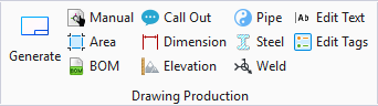
Drawing Production ribbon group
The BOM Area is considered a dynamic area where the OpenPlant Modeler program will output information from the actual model. Dynamic areas are defined using a name and a rectangular boundary. This boundary defines the limit for the drawing production procedure to fit the information. The name defines what information needs to be placed where.
Open a Template Drawing
Before creating a BOM area, the user must first open a support drawing template drawing.
A default drawing production template named OPSE_DrawingProduction.dgn is included with the OpenPlant Modeler install. This drawing is stored in the following location:
C:\ProgramData\Bentley\OpenPlant CONNECT Edition\Configuration\WorkSpaces\OpenPlantExample\WorkSets\Imperial\Standards\OpenPlant\Seed\Others\
Below is the snapshot of the template drawing shipped with OpenPlant Modeler with the default areas. These areas are visible if DPTemplate Layer is switched ON.
The BOM area can be drawn, resized, moved etc. in the template drawing, then saved to the original default template, or as a new template drawing.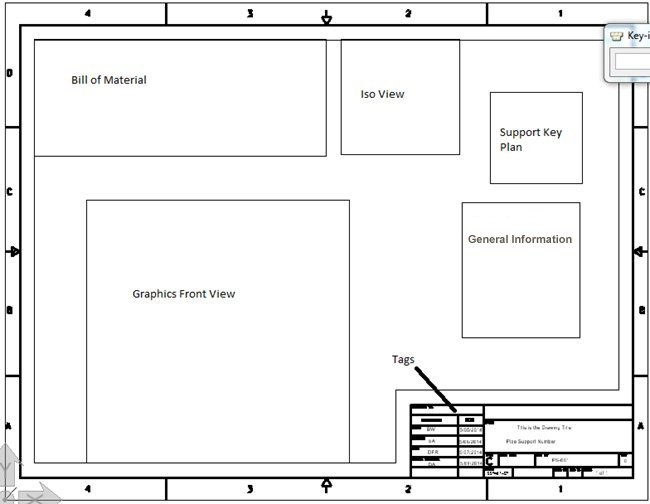
Customizing the BOM Area
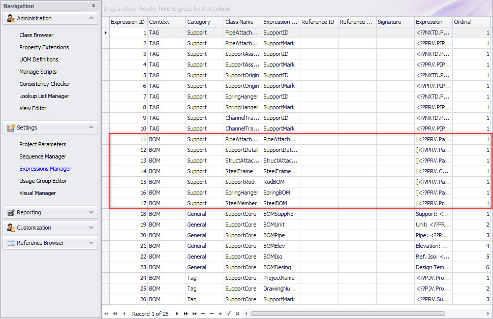
The BOM area is customizable using the Expression Manager in the Project Dashboard as shown below. The rows where Context =BOM and Category=Support are used to populate the Bill of Material Area defined in the support template drawing. In image below one can see only six entries but they are covering all of the support classes as these are the parent nodes in various support class hierarchy. These base classes can be further customized or individual classes can be added to override the parent Expression.
BOM Expressions
The expressions defined in the Expressions Manager, determine what is output to the BOM area in a Support Drawing.
See the following example defined for the PipeAttachment class to see what will appear on the output drawing:
[<??PRV.PartType> <??PRV.CatalogTag>] <??PRV.Description> <??PRV.PrimSize> <??PRU.PrimSize>
All the classes that are directly attached to pipe are under the PipeAttachment. So for clamps, HoldDowns and PipeClevis, this expression will get executed and results will be shown in the output drawing.
<??PRV.PartType> will get replaced by the partype property value for the selected support during the support drawing execution.
Using this format one can output the desired component properties in the output.
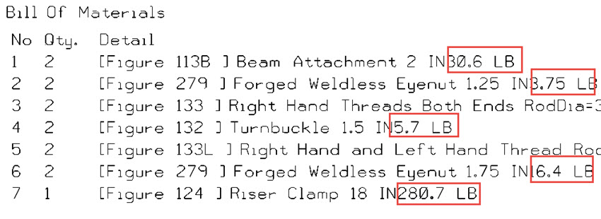
BOM Weight Expression
To add Weight to BOM entries, add the following to each BOM expression in the Expressions Manager section of the Project Dashboard:
<??PRV.Weight><??PRU.Weight>
Save the changes. The next time a support drawing is generated, the weight should display in the BOM:
BOM Text Size
The user is able to control the text size in the BOM using the following Project Dashboard > Support Drawing parameters:
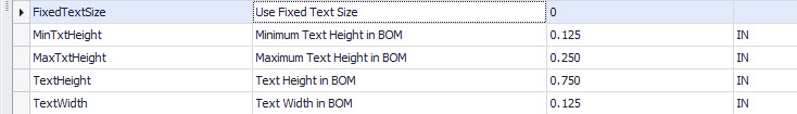
| Setting | Description |
|---|---|
| FixedTextSize | When set to 0, the application will use the Min and
Max text height values to determine a default text size for the BOM..
When set to 1, the values set for the Text Height and Text Width variables will be used. |
| MinTxtHeight | Defines a minimum text height for OPSE to use when determining a default text size. |
| MaxTxtHeight | Defines a maximum text height for OPSE to use when determine a default text size. |
| TextHeight | Actual Text Height used for BOM when the FixedTextSize value is set to 1. |
| TextWidth | Actual Text Width used for BOM when the FixedTextSize value is set to 1. |